Layer 2 Security - L2TPv3 for Disaster Recovery Sites
It's been a while since we talked about Layer 2 Security, I thought that today we might talk about how this applies to Disaster Recovery Sites and processes.
A common requirement for today's Datacenters is a DR (Disaster Recovery) site - a secure, remote location that has a full copy of the critical servers in the primary Datacenter. The DR site is generally kept to some level of currency, usually the IT group tries to keep the DR servers either within 15, 30 or 60 minutes of the primary servers, or replication happens in the evening when WAN traffic is light, and the DR Servers are at last night's timeframe. Replication can use things like replication tools for virtual or physical hosts, stretch clusters or SAN mirroring.
Replication aside, a common problem with DR sites is that you can't have a discontiguous subnet in a routed network. What is meant by that is - if your datacenter is 192.168.10.0/24, you can't have your DR site use that same subnet if you have a routed network between the two sites. So in a routed network the DR site and the Primary Datacenter need to use different subnet addresses. There are three main implications for DR that this drives out:
a/ if you declare a disaster, you need to take the primary datacenter offline, and give the DR site that subnet address
b/ this means that there's a significant manual effort to re-address and re-route all the affected subnets
c/ this also means that it's next to impossible to declare a disaster that only affects one or a few servers.
So, is there a way around this, besides buying a new network that will allow you to bridge rather than route between the two subnets? As you've guessed from the title of this article, yes, you can use L2TPv3 (Layer Two Tunnelling Protocol, Version 3) to do exactly this. On a routed network, L2TPv3 will build a virtual bridge between the two sites.
Let's run through an example configuration, then discuss how it's built - - first, the network diagram:
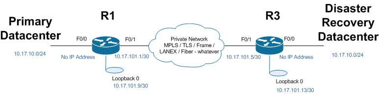
You can see that the primary and DR Datacenters have the same ip subnet (10.17.10.0/24), but are separated by some arbitrary WAN network
The config snips that build the tunnel that bridges the two datacenters are:
| Router R1: | |
| pseudowire-class DRPATH | Define the “pseudo wire” that will link the two sites and carry the bridged traffic |
| encapsulation l2tpv3 | Encapsulate it using l2tpv3 |
| ip local interface Loopback0 | Which interface is this tied to? Loopbacks are normally used, in this example we could have used F0/1 as well. |
| interface FastEthernet0/0 | This is the "inside" interface, facing the primary datacenter vlan |
| no ip address | Remove the ip address (remember that this is a bridged solution) |
| xconnect 10.17.101.13 101 pw-class DRPATH | Cross connect the pseudo-wire to the ip address at the far end |
| interface loopback0 | Define and address the loopback used to tie the PW to |
| ip address 10.17.101.9 255.255.255.252 | |
| iInterface FastEthernet0/1 | This is the "outside" interface, facing the WAN |
| ip address 10.17.101.1 255.255.255.252 | The “outside” interface needs a routable ip |
| ip route 10.17.101.4 255.255.255.252 10.17.101.2 | Define the routes to the far end (the DR site). On most networks you would do this with a routing protocol such as OSPF or BGP |
| ip route 10.17.101.12 255.255.255.252 10.17.101.2 | |
| Router R3: | |
|
|
|
interface FastEthernet0/0 no ip address xconnect 10.17.101.9 101 pw-class DRPATH |
|
interface FastEthernet-/1 ip address 10.17.101.5 255.255.255.252 |
|
int Loopback0 ip address 10.17.101.13 255.255.255.252 |
|
ip route 10.17.101.0 255.255.255.252 10.17.101.6 ip route 10.17.101.8 255.255.255.252 10.17.101.6 |
As you'll see, the L2Tpv3 tunnel is usually tied to a loopback address. Because loopbacks are logical interfaces, they are not subject to media failures, they remain up no matter what (unless you shut them down manually) This allows you a simple way of handling backup and load balanced paths - as long as the respective loopback ip's are routed through both a primary and backup path, the config is tremendously simplified.
Almost every networking vendor supports L2TPv3 - it's standards based, described in RFC3931, and is pretty easy on the router/switch CPU. L2TPv3 is also encryptable - so if the goal is to communicate to the DR site over a public network (like the public internet for instance), the data in transit can be encrypted using standard VPN algorithms (we hope that you're using at least AES256). L2TPv3 can also be prioritized - so, using time based access lists (TBACL), you can for instance run replication at a lower priority during the day, giving priority to VOIP and business apps, then crank the priority up in the evening to catch up on replication of larger servers - just be sure that your time services are solid before you take this route ! Authentication and a truckload of other features are also supported - none of these are covered in this article, what we're describing here is a very basic configuration only.
Things to watch out for - as in any protocol, compromises are made as the protocol is designed, and you'll want to be aware of some of these when you implement. L2TPv3 has some overhead (it varies, depending on how you implement it). Also, L2TPv3 is perfectly happy to carry spanning tree BPDU's (Bridge Protocol Datagram Units) - so if you have a potential loop built with a fiber primary and L2TPv3 backup for instance, be sure to factor that into your layer two design.
Other protocols that could be used to deliver similar functions are Ethernet over MPLS and 802.1QinQ tunnelling (commonly called QinQ). The downside of these is that they both require support from the service provider. This means that they'll typically cost money, and generally can't be deployed over public internet. They're also tough to troubleshoot if you provider makes a config change that breaks things on you a few months after it's running (guaranteed at least a few hours of finger pointing before you start fixing anything!).
L2TPv3 allows you to dramatically simplify the networking requirements for DR. With the prevalence of Virtual Datacenters now, it's very common to see a rack of servers running VMs as a primary datacenter, and a smaller rack of servers running the DR site. Given the replication tools, and now simplified networking, the technical delivery of a DR site can easily be a short 1-2 week project.
Just be sure that you don't treat DR as a purely technical IT project. Be sure to involve other groups in the business, have them dictate the SLA's for server currency, what services are critical, when to declare emergencies and the rest. Also be sure not to go overboard on using old gear at the DR site. Remember, everything data-wise that is at the primary site is also at the DR site - you need the same security controls, change control and the rest at the DR site as you have at the primary, or you've just spent a large effort building a nice backdoor for whoever wants to use it !
=============== Rob VandenBrink, Metafore ================


Comments